SPECIFICATIONS
Material

General Specifications

Torque Specifications

a Refer to the procedure in this section.
DESCRIPTION AND OPERATION
Engine Ignition
3.5L GTDI


System Operation
Refer to the PC/ED manual section 1 Description and Operation.
Component Description
Refer to the PC/ED manual section 1 Description and Operation.
DIAGNOSIS AND TESTING
Engine Ignition
For PCM DTCs, REFER to Section 303-14 PCM DTC Chart. For driveability symptoms without DTCs, refer to the PC/ED manual, section 3 Symptom Charts.
REMOVAL AND INSTALLATION
Engine Ignition Components - Exploded View
3.5L Gasoline Turbocharged Direct Injection (GTDI) LH Side


3.5L GTDI RH Side


- Refer to the procedures and/or exploded views in this section for any Warnings, Notices, Notes, Materials, Specifications, and Special Tools. Items in the exploded views may not be listed in order of removal.
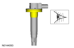
Ignition Coil-On-Plug - 3.5L GTDI
Material

Removal and Installation
WARNING: Before beginning any service procedure in this section, refer to Safety Warnings in Section 100-00. Failure to follow this instruction may result in serious personal injury.
NOTE: Removal steps in this procedure may contain installation details.
LH side

- NOTE: When removing or installing the fuel injection pump noise insulator, spreading the openings will reduce the risk of damage.

RH side
- NOTE: When installing, align the index marks.
- Tighten to 5 Nm (44 lb-in).

-
- Tighten to 6 Nm (53 lb-in).

- NOTE: When installing, align the index marks.
- Tighten to 5 Nm (44 lb-in).

Both sides
- NOTE: Use compressed air to remove any foreign material from the
ignition coil-on-plugs and surrounding area before removing the ignition
coil-on-plugs.
NOTE: When removing the ignition coil-on-plugs, a slight twisting motion will break the seal and ease removal.
NOTE: When installing the ignition coil-on-plugs, apply a small amount of silicone brake caliper grease and dielectric compound to the inside of the ignition coil-on-plug boots before installation. Material: Silicone Brake Caliper Grease and Dielectric Compound XG-3-A.
Tighten in the following 2 stages.- Stage 1: Tighten to 7 Nm (62 lb-in).
- Stage 2: Tighten an additional 50 degrees.

Installation
- Replace any ignition coil-on-plug seals with cracks, rips, or tears.
- To install, reverse the removal procedure.
Spark Plugs - 3.5L GTDI
Removal and Installation
WARNING: Before beginning any service procedure in this section, refer to Safety Warnings in Section 100-00. Failure to follow this instruction may result in serious personal injury.
NOTE: Removal steps in this procedure may contain installation details.
- Remove the 6 ignition coil-on-plugs, refer to Ignition Coil-On-Plug - 3.5L GTDI.
- NOTICE: Only use hand tools when removing or installing the
spark plugs, or damage may occur to the cylinder head or spark plug.
NOTICE: The spark plug procedure must be followed exactly or damage to the cylinder head and spark plug will result.
NOTICE: Do not remove the spark plugs when the engine is hot or cold soaked. Spark plug thread or cylinder head damage can occur. Make sure the engine is warm (hand touch after cooling down) prior to spark plug removal.
NOTICE: The spark plug must be securely held in an assembly aid or tool to prevent the spark plug from falling into the spark plug well which may damage the spark plug or the cylinder head.
NOTICE: If a spark plug is dropped, internal damage may result and the spark plug must be discarded. The use of a damaged spark plug may cause engine damage to occur.
NOTE: Use compressed air to remove any foreign material in the spark plug well before removing the spark plugs.
- Tighten to 15 Nm (133 lb-in).

Installation
- To install, reverse the removal procedure.
 Engine Ignition - 3.5L Ti-VCT
SPECIFICATIONS
Material
General Specifications
Torque Specifications
DESCRIPTION AND OPERATION
Engine Ignition
Component Location
System Operation
REFER to the PC/ED manual
section 1 D ...
 Engine Ignition - 2.0L GTDI
SPECIFICATIONS
Material
General Specifications
Torque Specifications
DESCRIPTION AND OPERATION
Engine Ignition
Component Location
System Operation
REFER to the PC/ED manual
sect ...
Other materials:
Diagnosis and Testing
Automatic Transmission
Special Tool(s)
Material
DTC Chart
Diagnostics in this manual assume a certain skill level and knowledge of
Ford-specific diagnostic practices. Refer to Diagnostic Methods in Section
100-00 for information about these practices.
When the electrical connector ...
Sitting in the correct position
WARNING: Sitting improperly out of position or with the seat
back reclined too far can take off weight from the seat cushion
and affect the decision of the passenger sensing system, resulting in
serious injury or death in a crash. Always sit upright against your seat
back, with your feet on the ...
Safety Warnings
Review carefully the General Service Health and Safety Precautions below before
beginning any repair. Following these general service warnings are specific
system warnings that must be carefully reviewed before beginning work on any
listed system.
General Service Health and Safety Precautions
& ...
